Constructing a J-Pole Antenna: A Guide for Ham Radio Operators
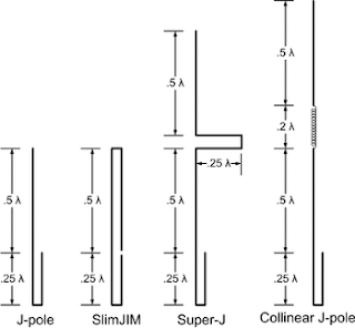
The J-pole antenna is a type of end-fed antenna that is popular among ham radio operators for 2m and 70 cm operations. It consists of two parallel conductors, with the top section being a half-wave element and the bottom section being a quarter-wave matching stub. The name "J-pole" comes from the shape of the antenna, which looks like the letter "J" when it is bent at the bottom. One of the key features of the J-pole antenna is its omnidirectional radiation pattern. This means that the antenna can transmit and receive signals equally well in all directions, making it a great choice for general communication purposes. Another advantage of the J-pole antenna is that it does not require any radials or ground plane, which reduces the wind resistance and simplifies the installation process. To construct a J-pole antenna, we first need to determine the length of the half-wave element. This can be calculated using the formula: Length = 468 / frequency in MHz For example, i...


