Constructing a J-Pole Antenna: A Guide for Ham Radio Operators
The J-pole antenna is a type of end-fed antenna that is popular among ham radio operators for 2m and 70 cm operations. It consists of two parallel conductors, with the top section being a half-wave element and the bottom section being a quarter-wave matching stub. The name "J-pole" comes from the shape of the antenna, which looks like the letter "J" when it is bent at the bottom.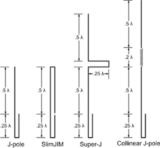
One of the key features of the J-pole antenna is its omnidirectional radiation pattern. This means that the antenna can transmit and receive signals equally well in all directions, making it a great choice for general communication purposes. Another advantage of the J-pole antenna is that it does not require any radials or ground plane, which reduces the wind resistance and simplifies the installation process.
To construct a J-pole antenna, we first need to determine the length of the half-wave element. This can be calculated using the formula:
Length = 468 / frequency in MHz
For example, if we want to build a J-pole antenna for the 2m band (144 MHz), the length of the half-wave element would be:
Length = 468 / 144 = 3.25 feet
Next, we need to calculate the length of the quarter-wave matching stub. This can be done using the formula:
Length = 234 / frequency in MHz
For the same 2m band example, the length of the matching stub would be:
Length = 234 / 144 = 1.625 feet
Once we have determined the lengths of the two sections, we can construct the antenna by connecting them together at the bottom using a shorting bar or wire. The coaxial feedline is then attached to the antenna at a point along the matching stub, where the impedance is at its lowest.
To ensure optimal performance, it is important to keep the two parallel conductors of the J-pole antenna away from other conducting materials by a distance of two to three times the spacing between the conductors. Additionally, there should be a non-conducting free space between the antenna conductors and the mounting structure to minimize any potential interference. The separation between the two conductors should not be more than 2% of the wavelength.
A coil of coax at the feedpoint can also serve as a choke to prevent radiofrequency from traveling down along the feedline.
In terms of gain, the J-pole antenna typically has a gain of about 2dB compared to a quarter-wave ground plane antenna. The gain is slightly more on the side of the J stub compared to the opposite side.
Overall, the J-pole antenna is a popular and effective choice for ham radio operators looking for an omnidirectional antenna that is easy to construct and does not require any additional ground plane or radials. With the right calculations and construction techniques, anyone can build their own J-pole antenna and enjoy clear and reliable communication on the 2m and 70 cm bands.


Comments
Post a Comment